Stm32 и arduino: сравнение характеристик, плюсы и минусы
Содержание:
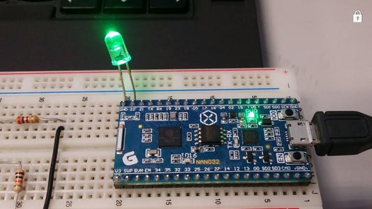
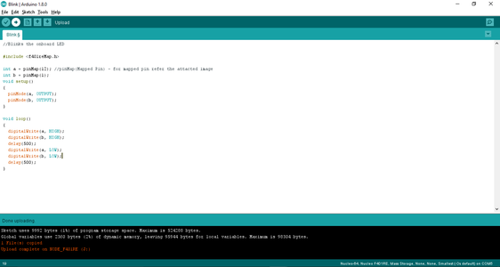
Step 4: Blink Example
Before going to the coding part, firstly we have to select the Board and the port to which the board has been connected. For this;
Click on «Tools», click on «Board»- a drop-down box appears. scroll down and navigate to Nucleo-X (in my case, it is Nucleo-64) and select it, click on «Tools», click on «Board part number» and select your board (in my case, it is Nucleo F401RE) and again click on «Tools», click on «Port» and select the port on which your Nucleo board is mounted.
Now, let’s head towards the coding part;
The source code for the basic blink program;
//Program to blink the onboard LED
#include <f401reMap.h>
int a = pinMap(12); //pinMap(Mapped Pin) — for mapped pin refer the attacted image
int b = pinMap(1);
void setup()
{
pinMode(a, OUTPUT);
pinMode(b, OUTPUT);
}
void loop()
{
digitalWrite(a, HIGH);
digitalWrite(b, HIGH);
delay(500);
digitalWrite(a, LOW);
digitalWrite(b, LOW);
delay(500);
}
Using serial port (not just for debugging)
Zoom in
In your code, create a Serial object (using TX and RX pin names of the connected serial port).
Use printf function to send serial messages to the connected PC.
Sending debug messages over the ST-Link virtual com port
| STM32F103C8T6 board, pin PA_2 (Serial2 TX) | <=> | NUCLEO board CN3 connector, pin RX |
| STM32F103C8T6 board, pin PA_3 (Serial2 RX) | <=> | NUCLEO board CN3 connector, pin TX |
A smart trick proposed by Nothing Special makes even soldering needless.
The point is to redirect the UART on the NUCLEO board by software (without modifying the solder bridges on the back side of the NUCLEO board) and convert it into a «Debugger». On the NUCLEO board that you are going to use as programmer/ debugger, choose any Serial port other than Serial2 (other than the default port used for standard UART) to be initialized as standard UART. In the program below (using NUCLEO-F103RB as programmer/debugger) Serial1 (PA_9, PA_10) was selected.
Debugger
#include "mbed.h"

// declarations needed to change the parameters of stdio UART
extern serial_t     stdio_uart;
extern int          stdio_uart_inited;

int main() {
    serial_init(&stdio_uart, PA_9, PA_10); // other than Serial2
    stdio_uart_inited = 1;
    printf("Ready for debugging\r\n");
}
Once compiled (remember to select the NUCLEO board used for programing/debugging as target for the online compiler), download the «Debugger» program to the NUCLEO board. Please make sure you have the two jumpers in place on the CN2 connector when programming the NUCLEO board. Once the «Debugger» binary has been downloaded to the NUCLEO board, remove the two jumpers again.
Using the mbed online compiler to build programs for the STM32F103C8T6 board
Create a program as if it was for a NUCLEO-F103RB board (select NUCLEO-F103RB as target platform for the online compiler).
Or click to import this demo into your online compiler.
Blinking on-board LED:
#include "mbed.h"

Serial      pc(PA_2, PA_3); // TX, RX
DigitalOut  myled(PC_13);   // on-board LED

int main()
{
    while(1) {
        // The on-board LED is connected via a resistor to +3.3V (not to GND).
        // So the LED is active on 0
        myled = 0;      // turn the LED on
        wait_ms(200);   // wait 200 millisecond
        myled = 1;      // turn the LED off
        pc.printf("Blink\r\n");
        wait_ms(1000);  // wait 1000 millisecond
    }
}
Warning
Keep in mind that the online compiler is checking for 128kB maximum flash size. However, the STM32F103C8T6 is equipped with only 64kB. Although it seems that majority of Blue Pill boards sold online usually feature 128kB Flash rather than 64kB. Once the compilation is complete (started by clicking on the Build only button in the Compile drop list or by pressing Ctrl+B) you can visually check the size of used flash memory in the Program details — Build tab. In order to fit into an STM32F103C8T6 board the used Flash should not exceed 64kB (depending on your actual board). Try to optimize your program until it’s using less than 64kB flash memory. Have a look at mbed-STM32F030F4 and Andy’s hints for some good tips.
Supported boards
| Status | Device(s) | Name | Release | Notes |
|---|---|---|---|---|
| STM32F207ZG | 0.2.0 | |||
| STM32F429ZI | 0.1.0 | |||
| STM32F767ZI | 1.4.0 | |||
| STM32F746ZG | 1.9.0 | |||
| STM32F756ZG | 1.9.0 | |||
| STM32L496ZG | 1.3.0 | |||
| STM32L496ZG-P | 1.3.0 | |||
| STM32L4R5ZI | 1.4.0 | |||
| STM32L4R5ZI-P | 1.4.0 | |||
| STM32H743ZI | 1.5.0 | Nucleo H743ZI2 since 1.6.0 |
| Status | Device(s) | Name | Release | Notes |
|---|---|---|---|---|
| STM32F030R8 | 0.2.0 | |||
| STM32F072RB | 1.9.0 | |||
| STM32F091RC | 0.1.0 | |||
| STM32F103RB | 0.2.0 | |||
| STM32F302R8 | 1.1.0 | |||
| STM32F303RE | 0.1.0 | |||
| STM32F401RE | 0.2.1 | |||
| STM32F411RE | 0.2.1 | |||
| STM32F446RE | 1.1.1 | |||
| STM32G071RB | 1.6.0 | |||
| STM32G431RB | 1.7.0 | |||
| STM32G474RE | 1.7.0 | |||
| STM32L053R8 | 0.1.0 | |||
| STM32L073RZ | 1.4.0 | |||
| STM32L152RE | 1.0.0 | |||
| STM32L433RC-P | 1.9.0 | |||
| STM32L452RE | 1.5.0 | |||
| STM32L452RE-P | 1.8.0 | |||
| STM32L476RG | 0.1.0 | |||
| STM32WB55RGSTM32WB55CG | 1.6.0 | No BLE support |
| Status | Device(s) | Name | Release | Notes |
|---|---|---|---|---|
| STM32F031K6 | 1.9.0 | |||
| STM32F303K8 | 1.1.0 | |||
| STM32G431KB | 1.7.0 | |||
| STM32L031K6 | 1.1.1 | |||
| STM32L412KB | 1.5.0 | |||
| STM32L432KC | 0.2.0 |
| Status | Device(s) | Name | Release | Notes |
|---|---|---|---|---|
| STM32F030R8 | 1.3.0 | |||
| STM32F072RB | 1.5.0 | |||
| STM32F100RB | 0.2.1 | |||
| STM32F407VG | 0.1.0 | |||
| STM32F746NG | 0.1.0 | |||
| STM32G031J6 | 1.9.0 | |||
| STM32L072CZ | 1.1.0 | |||
| STM32L475VG | 1.0.1 | |||
| STM32F413ZH | 1.9.0 | |||
| STM32L4S5VI | 2.0.0 |
| Status | Device(s) | Name | Release | Notes |
|---|---|---|---|---|
| STM32L4R9ZI | 1.7.0 |
| Status | Device(s) | Name | Release | Notes |
|---|---|---|---|---|
| STM32MP157A | 1.8.0 | See the documentation to use this board | ||
| STM32MP157C | 1.8.0 | See the documentation to use this board |
Generic STM32F1 boards
| Status | Device(s) | Name | Release | Notes |
|---|---|---|---|---|
| STM32F103C6STM32F103C8STM32F103CB | 1.2.0 | USB CDC support since 1.5.0 Maple bootloaders support since 1.6.0 | ||
| STM32F103C8STM32F103CB | 1.5.0 | |||
| STM32F103C4STM32F103C6STM32F103C8STM32F103CB | Generic Board | 1.9.0 | ||
| STM32F103R6STM32F103R8STM32F103RBSTM32F103RCSTM32F103RDSTM32F103RESTM32F103RFSTM32F103RG | 1.9.0 | |||
| STM32F103T4STM32F103T6STM32F103T8STM32F103TB | Generic Board | 1.9.0 | ||
| STM32F103V8STM32F103VBSTM32F103VCSTM32F103VDSTM32F103VESTM32F103VFSTM32F103VG | Generic Board | 1.9.0 | ||
| STM32F103ZCSTM32F103ZDSTM32F103ZESTM32F103ZFSTM32F103ZG | Generic Board | 1.9.0 | ||
| STM32F103TB | HY-TinySTM103T | 1.5.0 | ||
| STM32F103CB | Maple Mini | 1.2.0 | ||
| STM32F103ZE | 1.9.0 | |||
| STM32F103ZE | vcc-gnd.com Mini | 1.9.0 |
Generic STM32F4 boards
| Status | Device(s) | Name | Release | Notes |
|---|---|---|---|---|
| STM32F405RG | 1.8.0 | |||
| STM32F401CC | 1.7.0 | More info | ||
| STM32F411CE | 1.9.0 | More info | ||
| STM32F407VESTM32F407VG | 1.4.0 | STM32F407VG support since 1.5.0 | ||
| STM32F407ZESTM32F407ZG | Black F407ZE / Black F407ZG | 1.5.0 | ||
| STM32F407VE | 1.4.0 | |||
| STM32F401RC | 1.7.0 | |||
| STM32F407VG | 1.5.0 | |||
| STM32F407VE | 1.5.0 | |||
| STM32F401CBSTM32F401CCSTM32F401CDSTM32F401CE | Generic Board | 1.9.0 | ||
| STM32F401RBSTM32F401RCSTM32F401RDSTM32F401RE | Generic Board | 1.8.0 | ||
| STM32F405RG | Generic Board | 1.9.0 | ||
| STM32F407VESTM32F407VG | Generic Board | 1.9.0 | ||
| STM32F410C8STM32F410CB | Generic Board | 1.9.0 | ||
| STM32F410R8STM32F410RB | Generic Board | 1.9.0 | ||
| STM32F411CCSTM32F411CE | Generic Board | 1.9.0 | ||
| STM32F411RCSTM32F411RE | Generic Board | 1.9.0 | ||
| STM32F412CESTM32F412CG | Generic Board | 1.9.0 | ||
| STM32F412RESTM32F412RG | Generic Board | 1.9.0 | ||
| STM32F413CGSTM32F413CH | Generic Board | 1.9.0 | ||
| STM32F413RGSTM32F413RH | Generic Board | 1.9.0 | ||
| STM32F415RG | Generic Board | 1.9.0 | ||
| STM32F417VESTM32F417VG | Generic Board | 1.9.0 | ||
| STM32F423CH | Generic Board | 1.9.0 | ||
| STM32F423RH | Generic Board | 1.9.0 | ||
| STM32F446RCSTM32F446RE | Generic Board | 1.9.0 | ||
| STM32F411CE | ThunderPack v1.1+ | 1.9.0 |
3D printer boards
| Status | Device(s) | Name | Release | Notes |
|---|---|---|---|---|
| STM32F407VE | ARMED V1 | 1.5.0 | ||
| STM32F030 | EExtruder F030 V1 | 1.5.0 | Small companion board for Prntr Board V1 | |
| STM32F103C8 | 1.5.0 | |||
| STM32F070C8 | 1.5.0 | |||
| STM32F070C8 | 1.8.0 | |||
| STM32F407VE | Prntr Board V1 | 1.5.0 | ||
| STM32F407VE | Prntr Board V2 | 1.8.0 | ||
| STM32F765VI | RemRam v1 | 1.4.0 | ||
| STM32F446VE | RUMBA32 | 1.5.0 | ||
| STM32F401VE | 1.6.0 | |||
| STM32F446RE | 1.6.0 | |||
| STM32F446VE | 1.9.0 |
LoRa boards
| Status | Device(s) | Name | Release | Notes |
|---|---|---|---|---|
| STM32F072C8STM32F072CB | Elektor LoRa Node | 1.8.0 | ||
| STM32L151RB | 1.4.0 | |||
| STM32L051C8 | 1.7.0 | Basic support |
Generic flight controllers
| Status | Device(s) | Name | Release | Notes |
|---|---|---|---|---|
| STM32F103CB | Afro Flight Rev5 (8/12MHz) | 1.7.0 | ||
| STM32F303CC | Sparky V1 | 1.6.0 |
| Status | Device(s) | Name | Release | Notes |
|---|---|---|---|---|
| STM32F072RB | 1.9.0 | More info | ||
| STM32F401CE | 1.9.0 | More info | ||
| STM32F411RE | 1.9.0 | More info | ||
| STM32F412RE | 1.9.0 | More info |
| Status | Device(s) | Name | Release | Notes |
|---|---|---|---|---|
| STM32WB55CG | 1.7.0 |
Programming the STM32F103C8T6 board
NUCLEO ST-LINK/V2-1 and drag & drop
You can use the NUCLEO virtual disk to program the STM32F103C8T6 board (drag and drop programming). To do that, an additional NUCLEO board is needed (any type equipped with ST-LINK/V2-1 will do).
Remove the two jumpers from the CN2 connector as illustrated in Figure 8:
Connect the NUCLEO board CN4 connector to the STM32F103C8T6 board using flying wires as follows:
| NUCLEO board CN4 connector | STM32F103C8T6 debug connector | STM32F103C8T6 board | |||||
|---|---|---|---|---|---|---|---|
| SWCLK | <=> | DCLK | |||||
| GND | <=> | GND | |||||
| SWDIO | <=> | DIO | |||||
| NRST | <=> | RESET |
Warning
Please notice that is not connected. That works with the ST-Link programmer but could potentially damage the target micro controller in case it’s running at a lower voltage (e.g. 2V5) than the programmer (e.g. 3V3). That’s why it’s recommended to connect also the line when an external programmer such as a Segger J-Link is hooked up to program the board.
- Provide power for the STM32F103C8T6 board through a 3.3V pin, 5V pin or over a USB cable. (The VDD_TARGET pin on the NUCLEO board CON4 does not work as source of power).
- Connect the NUCLEO board to your PC over a USB cable.
Board pinout
Information
Only the labels printed in blue/white or green/white (i.e. PC_13, PB_9, A0, D14 …) must be used in your code. The other labels are given as information (alternate-functions, power pins, …). You can also use these additional pin names:
LED1=PC_13  SERIAL_TX=PA_2  I2C_SCL=PB_8  SPI_MOSI=PA_7  PWM_OUT=PB_3
            SERIAL_RX=PA_3  I2C_SDA=PB_9  SPI_MISO=PA_6
                                          SPI_SCK =PA_5
                                          SPI_CS  =PB_6
Please notice that in order to fit the small size board, the leading ‘P’ and the ‘_’ characters are omitted from labels indicated on the board (e.g. Instead of ‘PA_1’ you can find the label ‘A1’ on the board). Arduino (green/white) and the additional naming labels are not indicated on the board.
Also notice that the on-board LED is connected to pin PC_13 and, via a resistor, to +3.3V. So to turn the LED or you have to set the DigitalOut to or respectively.
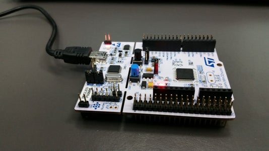
Introduction: Quick Start to STM Nucleo on Arduino IDE
 By sriksh9Srihari KoripalliFollow
More by the author:
About: Electronics hobbyist
More About sriksh9 »
Nucleo boards are the highly affordable and powerful boards from the ST Microelectronics. STM32 Nucleo boards allow anyone to try out new ideas and to quickly create prototypes with any STM32 MCU.
However, Arduino is unbeatable in this segment due its simplicity and ease of its IDE. The performance to the cost ration of the Arduino boards is very low, which make some hobbyists to look into other boards. STM has bought up the Nucleo development boards, whose performance to the cost ratio is pretty high as compared to that of Arduino.
Thanks to «STM32 Core» (Official) team for porting some of their popular Nucleo boards into Arduino IDE and helping all the Arduino users happy to the core.